
Above Help Centre
March 12, 2026 | 15-20 min read
Anomaly Types and Root Causes
Heated Module
A module showing anomalous heating across the entirety of its surface. Heated modules can have an intrinsic root cause, or heating can occur secondary to an extrinsic root cause. A common extrinsic root cause is 'string heating', where all modules in an electrical string are affected by a problem at the string level. String heating, in turn, may have an obvious visible cause (e.g. arboreal shading), or may require further investigation (e.g. 'open circuit strin
Root Cause
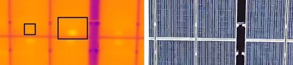
Individual module heating (Intrinsic)
No identifiable cause on RGB, may be:
‘Open circuit' module
Junction box issue
Activation of all three diodes
Damaged module (may be visible in RGB)
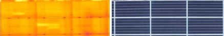
String Heating - a chain of heated modules corresponding to a string
String heating - no identifiable cause (typically “open circuit” string).
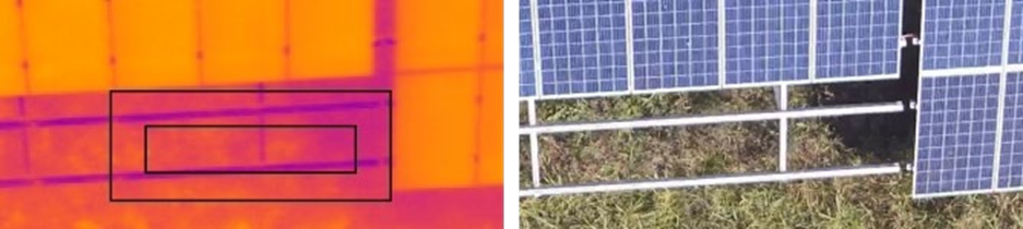
String heating - secondary to arboreal shading.
String heating - secondary to permanent shading.
String heating - secondary to damaged module (a single damaged module in a string can cause the whole string to heat).
String heating - secondary to missing module (a missing module can cause the whole string to heat if the string has not been reconnected correctly).
Combiner box-level anomaly - a large group of heated modules corresponding to a combiner box area.
Inverter-level anomaly - a large group of heated modules corresponding to an inverter area.
Transformer-level anomaly - a large group of heated modules corresponding to a transformer area.
Notes
Heated Modules are recorded regardless of temperature gradient relative to 'normal' module. The reference temperature will be recorded from the nearest unaffected module, which may not be within the image
The temperature gradient is not necessarily an indicator of power loss.
Occasionally module heating can occur across all the modules in a string, but in a heterogeneous 'multiple hot cell' pattern (rather than uniformly). This is typically caused by reverse polarity on the string, or may occur following lightning strike.
The reason that an open circuit substring, module or string is hotter than a normally working substring, module or string is that a proportion of the solar energy (radiation) hitting the surface (the cells) is no longer being converted into electricity and is therefore being absorbed as heat. The reason the gradient is relatively constant (approximately 4 to 10°C) in most given settings, is because the impact of the ambient temperature is theoretically neutral as both the working and the none working module are experiencing the same ‘base heat’ from the ambient air.
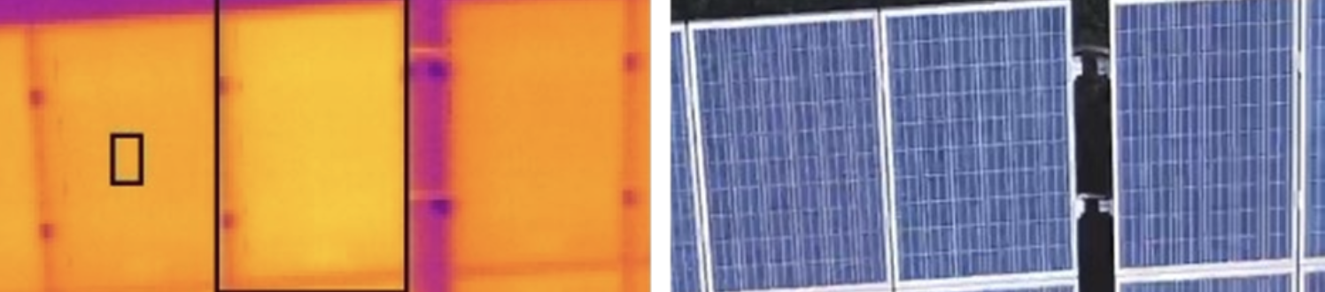
Heated Substring
One-third or two-thirds of the module appear heated (or other proportions, in newer module types e.g. half-cut modules).
Root Cause
Appropriate activation of diode (diode bypassing bad cells)
Malfunctioning diode
Loose connection
Lightning strike
Notes
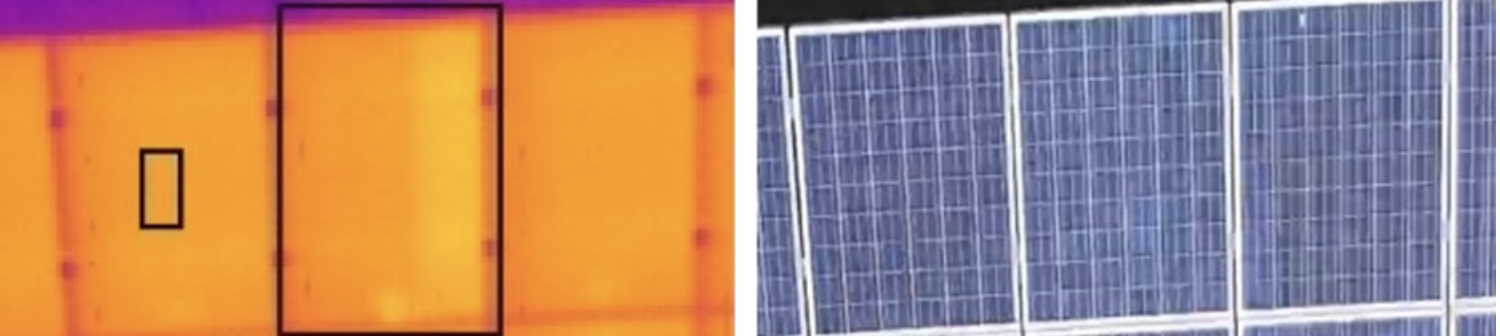
If the cause of the diode activation is visible and appropriate (e.g. soiling/hot spot), then the primary cause (the hot spot) is recorded, and the substring heating is NOT regarded as an anomaly.
If there is no obvious cause of diode activation, then a heated substring is recorded, regardless of temperature gradient. Further on-site investigation is required to differentiate appropriate vs anomalous substring heating, since this cannot be determined from UAV thermographic/RGB inspection alone.
Traditional 60- and 72-cell silicon module designs consist of three diodes, each protecting one-third of the module. Newer module designs (e.g. half-cut cell modules) may have 6 or more substring areas, which may be connected in more complex (series/parallel) configurations. These are currently also recorded as 'heated substring', but this is subject to regular review and more sophisticated anomaly types may be introduced.
The reason that an open circuit substring, module or string is hotter than a normally working substring, module or string is that a proportion of the solar energy (radiation) hitting the surface (the cells) is no longer being converted into electricity and is therefore being absorbed as heat. The reason the gradient is relatively constant (approximately 4 to 10°C) in most given settings, is because the impact of the ambient temperature is theoretically neutral as both the working and the none working module are experiencing the same ‘base heat’ from the ambient air.
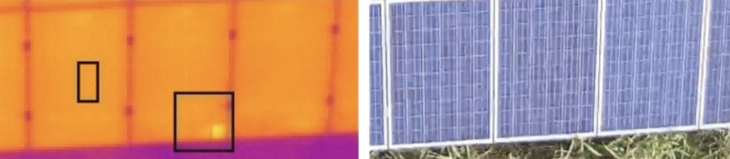
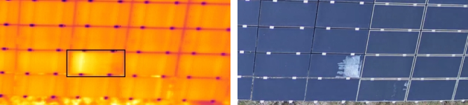
Hot Spot
Single heated area or cell.
Root Cause
Commonly identified from UAV inspections:
Soiling
Arboreal shading
Permanent shading
Damaged module
Usually only identifiable on further investigation:
Cell mismatch
Shunted cell
Cracked cell
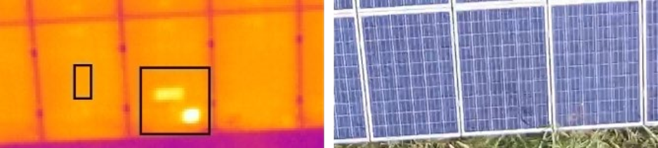
Multiple Hot Spots
More than one heated cell on a single module.
Root Cause
Commonly identified from UAV inspections:
Damaged module
Soiling
Arboreal shading
Permanent shading
Potential PID
Rear-side mismatch shading
Inverter-level anomaly
Usually only identifiable on further investigation:
Cell mismatch
Cracked glass
Combiner box anomaly
Rear-side mismatch shading
PID
Notes
Multiple hot cells are considered significant and recorded ifΔTm ≥ 4°C on silicon technology modules and ΔTm ≥ 3°C on thin-film technology modules.
Heated Junction Box
We record a heated junction box when it is significantly hotter than the average of the site. It is normal for the junction box to be slighter warmer than the module itself.
Root Cause
Junction box issue
Loose connection
Corrosion
Diode activated
Notes
Junction box heating is considered significant and recorded if ΔTm ≥ 7°C compared to a normal neighbouring junction box.
Heated Junction Boxes do not necessarily contribute to lost output, but in some circumstances can be a warning of problems to come
Heated Hypercell
A heated hypercell is a specific anomaly type seen in certain 'shingle-cell' type solar modules. These modules are typically divided into 18 hypercells, each of which can become heated.
Root Cause
Presumed to be caused by shingle-cell adhesive failure.
Missing Module
Used when a module is missing, but not by design (as determined by the provided CAD file).
Notes
The reference and target (peak) temperatures are set manually set so that ΔTm = 0°C
Tracker Fault
Tracker-array is not correctly tracking the sun.
Root Cause
Alignment failure
Mechanism failure
Notes
1. The reference and target (peak) temperatures are set manually set so that ΔTm = 0°C
Visual (thin-film modules)
A clear anomaly can be seen in the RGB image of a thin-film module.
Root Cause
Delamination
Damaged Module (Cracks)
Surface scratches
Notes
1. A visual anomaly is used in our specialist thin-film service, to indicate clear visible damage on a module, which doesn't necessarily cause a thermal anomaly
2. Visual anomalies are not generally used in non-thin-film inspections, except in the case of extreme visible damage that we think is important to highlight to the client.
Be part of the solar plant evolution.
See SolarGain in action, Our team is happy to help!